

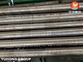
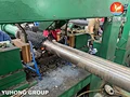

ASTM A213 T9 Studded Fin Tube for High-Temperature Flue Gas Systems
Overview: The Heat Transfer Surface Built for Dirty, Hot Flue Gas
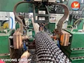
ASTM A213 T9 Studded Fin Tube is a composite heat transfer element engineered for the harshest segment of high-temperature flue gas systems: the convection section of fired heaters, waste heat recovery boilers, and FCC unit flue gas coolers where gas temperatures reach 550-600°C and the gas stream carries ash, catalyst fines, or unburned particulates . The base tube is seamless 9Cr-1Mo ferritic alloy steel per ASTM A213, selected for its creep strength and oxidation resistance at elevated temperature. The studs—round pins resistance-welded to the tube surface in a dense array—serve a dual function that no conventional fin can replicate: they increase the gas-side heat transfer area while maintaining an open, cleanable geometry that resists fouling and erosion .
The critical distinction from finned tubes is operational, not thermal. Finned tubes deliver higher surface area ratios (4-9× bare tube) but their thin fins erode rapidly in particle-laden gas and bridge with deposits that are difficult to remove . Studded tubes provide a lower but sustainable surface area multiplier (typically 2-3× bare tube), with thick cross-section studs that withstand abrasive particles and an open pitch that allows sootblowers or steam lances to reach the base tube surface . For engineers specifying convection section tubes, this is the fundamental trade-off: peak efficiency in clean gas versus predictable, maintainable performance in dirty gas.
Application & Compliance: Where It Is Used and What Problems It Solves
1. Refinery Fired Heater Convection Sections
Working Scenario: Crude heaters, vacuum heaters, and reformer furnaces. The convection section recovers heat from combustion gases before they exit the stack. Gas temperatures at the inlet of this section typically range from 550°C to 650°C, with velocities that carry ash and soot particles.
What it solves: The 9Cr-1Mo base tube provides the necessary creep and oxidation resistance at these temperatures . The studs create turbulence that disrupts the gas-side boundary layer, improving convective heat transfer without the fouling tendency of closely spaced fins. When deposits accumulate, the open stud pattern allows effective online sootblowing or offline water washing.
2. Waste Heat Recovery Boilers and HRSG Systems
Working Scenario: Heat recovery from gas turbine exhaust, incinerator flue gas, or process furnace off-gas. The tube bundle operates in the transition zone where gas temperature is still high enough to require alloy construction but low enough that acid dew point corrosion becomes a consideration at the cold end.
What it solves: T9’s chromium content (8-10%) provides sulfidation resistance superior to carbon steel in reducing/sulfur-bearing flue gas environments . Studded construction maintains heat recovery effectiveness even when gas cleanliness is variable, such as during sootblowing cycles or process upsets.
3. FCC Unit Flue Gas Coolers and Catalyst Handling
Working Scenario: Fluid catalytic cracking (FCC) flue gas contains fine catalyst particles that are highly abrasive. The tube surface must resist erosion from both the gas velocity and the cleaning medium.
What it solves: Abrasion resistance. The studs are thick (typically 6-12 mm diameter) and metallurgically bonded to the tube, unlike fins which are thin and prone to bending or erosion . In FCC service, studded tubes have demonstrated longer service life than finned alternatives, with the studs acting as sacrificial wear elements that protect the pressure boundary.
4. Why T9 and Why Studded? (Selection Rationale)
vs. Carbon Steel (A106/A192): Carbon steel lacks the high-temperature strength and oxidation resistance for sustained service above 450-500°C. T9’s 9% Cr provides a meaningful upgrade in creep life without the cost of higher-alloy grades (T22, T91).
vs. Finned Tube: In clean gas (e.g., air coolers, economizers downstream of particulate removal), finned tubes are the correct choice for maximum efficiency. In dirty, high-temperature flue gas where ash/catalyst deposition and erosion are present, studded tubes are the practical specification .
Technical Specifications & Material Data
1. Dimensional & Mechanical Properties
| Parameter | Specification |
|---|---|
| Base Tube Standard | ASTM A213 / ASME SA213 |
| Base Tube Grade | T9 (UNS K90941) |
| Base Tube OD | 25 mm – 219 mm |
| Base Tube Wall Thickness | 3.0 mm – 12.7 mm |
| Tube Length | Up to 18,000 mm (custom) |
| Stud Material | Carbon Steel / 13Cr / Alloy Steel (matched to service) |
| Stud Diameter | 5 mm – 20 mm |
| Stud Height | 5 mm – 35 mm |
| Stud Pitch | 8 mm – 30 mm (customizable) |
| Tensile Strength (base tube) | ≥ 415 MPa |
| Yield Strength (base tube) | ≥ 205 MPa |
| Elongation | ≥ 30% |
2. Chemical Composition (Base Tube T9, %)
| C (max) | Mn | P (max) | S (max) | Si | Cr | Mo |
|---|---|---|---|---|---|---|
| 0.15 | 0.30-0.60 | 0.025 | 0.025 | 0.25-1.00 | 8.0-10.0 | 0.90-1.10 |
3. Studded vs. Finned Tube: Application Selection
| Criterion | Studded Tube | Finned Tube |
|---|---|---|
| Gas cleanliness | Dirty, particle-laden | Clean or filtered |
| Max service temp | 650°C+ (base tube dependent) | Limited by fin attachment |
| Abrasion resistance | Excellent (thick studs) | Poor (thin fins erode) |
| Fouling resistance | Good (open geometry) | Moderate (fins bridge) |
| Cleaning tolerance | Withstands aggressive sootblowing | Requires careful handling |
| Surface area multiplier | 2-3× bare tube | 4-9× bare tube |
QA/QC & Certifications: Proof for Refinery and Power Project Approval
Studded tube integrity depends on the weld between stud and base tube. A single detached stud creates a hot spot and accelerates local corrosion. Our quality control addresses this directly.
Stud Weld Integrity: Automatic resistance welding produces a forge weld at each stud-to-tube interface. Pull tests and visual inspection are performed on production samples to verify weld strength .
Base Tube NDT: Seamless T9 tubes are tested per ASTM A213 requirements, including hydrostatic testing and eddy current or ultrasonic inspection for wall thickness and internal defects.
Material Test Certificates: EN 10204 3.1 MTC provided for both base tube and stud material, with heat number traceability.
Post-Studding Stress Relief: Alloy steel tubes are stress-relieved after studding per applicable code requirements to prevent delayed cracking in the weld zone .
Dimensional Inspection: Stud pitch, height, and diameter verified against project drawings. Tube straightness and end finish inspected.
Installation & Maintenance Guide (For EPC Contractors and Plant Operators)
Handling: Studded tubes are heavier and bulkier than bare or finned tubes. Lifting gear must be positioned to avoid point-loading on individual studs. Do not use studs as lifting points.
Welding (Tube-to-Tubesheet): The base tube is T9 (9Cr-1Mo), requiring preheat and controlled welding procedures similar to P91/P22 materials. Use matching filler metal (e.g., ER90S-B9 or equivalent) and maintain interpass temperature per the qualified WPS.
Cleaning: Studded tubes are designed for aggressive cleaning. Online sootblowing is effective. For offline cleaning, high-pressure water washing or steam lancing can be directed at the base tube between studs. Avoid mechanical scraping that could damage stud welds.
Inspection During Turnaround: Check for stud loss (detached or severely eroded studs), base tube wall loss at stud-to-tube fillets, and deposit bridging between studs. Localized stud loss is normal in high-wear zones; excessive loss indicates the need for tube replacement or upgrade to a higher-alloy stud material.
B2B Purchasing Terms & Commercial Conditions
MOQ (Minimum Order Quantity): 100 pieces or 500 kg per size/configuration. For refinery turnaround projects, smaller quantities can be negotiated from production runs.
FOB Lead Time:
Standard T9 base tube with carbon steel studs: 20–30 days.
Custom stud material (13Cr, alloy) or non-standard dimensions: 30–45 days after drawing approval and deposit.
Payment Terms: 30% T/T advance, 70% against copy B/L. L/C at sight acceptable for EPC contracts.
Packaging: Studded tubes are shipped in reinforced wooden cradles or steel frames. Studs are protected from impact during transit. End caps prevent moisture ingress. Bundle weights and dimensions provided for crane planning.
Documentation: MTC (3.1 or 3.2), stud weld procedure and qualification records, NDT reports, hydrostatic certificates, and dimensional inspection reports.
FAQ
Q1: Can we use T9 studded tubes in the convection section of a crude heater with gas inlet at 600°C?
A: Yes, this is within T9’s typical service range. The 9Cr-1Mo chemistry provides adequate creep strength and oxidation resistance at 600°C . Confirm the actual tube metal temperature and flue gas composition (especially sulfur content) with your process engineer, as sulfidation resistance may require a higher-alloy stud material.
Q2: Why not use finned tubes to get more surface area?
A: In dirty flue gas, finned tubes foul and erode. The fins bridge with deposits, reducing effectiveness, and thin fins wear through in abrasive service. Studded tubes provide lower but sustainable heat transfer with cleanability and mechanical durability . If the gas is genuinely clean, finned tubes are the better choice—but for convection sections of fired heaters and waste heat boilers, gas is rarely clean.
Q3: What stud material should we specify?
A: Carbon steel studs are standard for moderate-temperature, low-sulfur service. For higher corrosion resistance at temperature, 13Cr studs (13% chromium) provide better oxidation and sulfidation resistance . The stud material should be selected based on the flue gas composition and metal temperature, not simply matched to the base tube grade.
Q4: Do you provide U-bent studded tubes?
A: Yes, U-bending is available for studded tube configurations. The bend radius and stud-free zone at the bend must be specified on the drawing. Studs are typically omitted or shortened in the bend area to prevent interference and stress concentration.
Q5: What is the typical lead time for a refinery turnaround order?
A: For standard T9/carbon steel studded tubes, 20-30 days after drawing approval. Custom stud grades or non-standard dimensions: 30-45 days. We coordinate with turnaround schedules and can prioritize critical-path items where production capacity allows.


Comprehensive score