
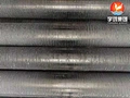
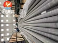
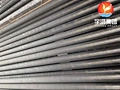
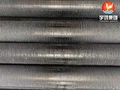
ASTM A249 TP304 G-Fin Embedded Aluminum Finned Tube for Boiler Economizers
Overview: The Heat Transfer Surface for Dirty, Cycling Flue Gas
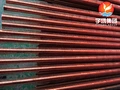
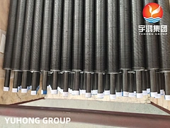
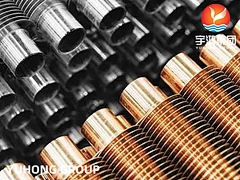
ASTM A249 TP304 G-Fin Embedded Aluminum Finned Tube is a composite heat transfer element specified for boiler economizers and waste heat recovery units where the flue gas is dirty enough to foul conventional fins but not hot enough to require welded stainless or alloy fin constructions. The base tube is welded austenitic stainless steel per ASTM A249 in TP304, selected for its resistance to condensate corrosion in the economizer’s cold-end zones and its stable supply chain availability in welded form. The aluminum fin is embedded—not merely wrapped—into a machined groove on the tube OD, with the groove closed by back-filling base tube material to mechanically lock the fin foot in place.
The engineering rationale for G-fin in economizer service is not maximum temperature capability. It is fin-bond durability under thermal cycling and cleanability in fouling service. Tension-wound L-foot fins rely on residual contact pressure at the fin foot; repeated heating and cooling in an economizer causes that pressure to decay, and the fin loosens before the tube itself reaches end of life. The G-fin’s mechanical embedment is insensitive to this relaxation mechanism. Simultaneously, the open fin pitch and absence of a continuous brazed or welded interface allow sootblowers and water washing to reach the base tube between fins, which is the practical requirement for coal, oil, and biomass flue gas paths.
The temperature boundary must be stated plainly: aluminum-fin G-fin tubes are practically limited to a fin-tip / tube-wall temperature in the range of 250–300°C in continuous service, with some suppliers permitting excursions toward 350°C depending on the base tube grade and the specific heat transfer conditions. Above that window, the aluminum fin loses strength and the tube-to-fin bond degrades regardless of embedment quality. For economizer sections operating above ~350°C gas-side, the correct upgrade is a high-frequency welded (HFW) or laser-welded fin tube, not a G-fin with a different alloy. This article addresses the applications where G-fin is the right specification—and where it is not.
Application & Compliance: Where G-Fin Earns Its Place in the Economizer
1. Coal, Oil, and Biomass Boiler Economizers (Moderate-Temperature Sections)
Working Scenario: The economizer recovers heat from flue gas downstream of the superheater or evaporator. Gas entering the G-fin section is typically in the 300–400°C range, with ash, soot, and acidic condensate potential at the cold end.
What it solves: The embedded fin foot does not loosen under the daily thermal cycling of load-following boilers. In dirty gas service, the fin pitch can be opened to a cleanable geometry without abandoning the heat transfer enhancement entirely. TP304 base tube provides condensate corrosion resistance superior to carbon steel in the cold-end rows where flue gas temperature drops toward the acid dew point.
2. HRSG and Waste Heat Recovery Economizers
Working Scenario: Gas turbine exhaust or process off-gas heat recovery, where gas temperature is lower than a fired boiler but fouling from unburned hydrocarbons or particulate may still be present.
What it solves: The G-fin’s mechanical bond tolerates the cyclic operation typical of HRSG service—frequent startups and shutdowns that would progressively loosen tension-wound fins. TP304’s oxidation resistance also provides margin during upset conditions when gas temperature briefly exceeds design.
3. Why Not L-Foot, KL, or Extruded?
L-Foot / KL: Maximum continuous temperature is lower (roughly 175–250°C), and the fin foot depends on residual tension. In economizer thermal cycling, L-foot fins are prone to loosening and the associated heat transfer penalty.
Extruded (Bimetallic): Offers excellent corrosion protection of the base tube because the aluminum sleeve encapsulates the tube entirely, but the cold-rolling process is limited in base tube materials and the maximum temperature is comparable to or lower than G-fin. It is the default for offshore/coastal air coolers, not for high-temperature flue gas economizers.
G-Fin (Embedded): The practical middle ground for economizers where gas is dirty, temperature is moderate, and thermal cycling is a design reality. It is not the right answer for clean gas (where a more efficient fin profile is acceptable) or for gas above ~350°C (where welded fins are mandatory).
4. Temperature Constraint in Practice
A boiler economizer handling flue gas at 350°C is frequently cited as the decision point where L-foot and even extruded fins become unsuitable, and G-fin or welded constructions are the practical options. However, the metal temperature at the fin is what governs aluminum fin performance, not the bulk gas temperature. In the colder rows of an economizer, G-fin with aluminum is well within its window. In the hotter rows, the design must either accept a shorter tube life or specify a welded fin tube with stainless or alloy fin material. This article and the associated product are offered specifically for the moderate-temperature, fouling-prone economizer sections where G-fin’s combination of cleanability and bond durability justifies its selection.
Technical Specifications & Fabrication Scope
1. Base Tube & Fin Configuration
| Parameter | Specification |
|---|---|
| Base Tube Standard | ASTM A249 / ASME SA249 |
| Base Tube Grade | TP304 (welded austenitic) |
| Base Tube OD | 25.4 mm – 63.5 mm (1"–2.5") standard; custom available |
| Base Tube Wall | 2.0 mm – 5.0 mm (selected to accommodate groove depth) |
| Fin Material | Aluminum 1060 / 1100 (standard); copper available on request |
| Fin Type | G-fin (embedded / grooved) |
| Fin Height | 10 mm – 16 mm |
| Fin Thickness | 0.35 mm – 0.50 mm |
| Fin Pitch | 4–8 fins per inch (customizable for cleanability) |
| Max Continuous Service Temp (Al fin) | 300°C practical; consult for 350°C excursions |
| Tube Length | Up to 18,000 mm |
| Groove Depth | ~0.4 mm typical |
2. G-Fin vs. Alternative Economizer Fin Types
| Criterion | G-Fin (Embedded) | L-Foot (Tension Wound) | HFW / Laser Welded |
|---|---|---|---|
| Fin bond mechanism | Mechanical embedment in groove | Residual contact pressure | Metallurgical weld |
| Thermal cycling resistance | Good (bond insensitive to relaxation) | Poor (contact pressure decays) | Excellent |
| Max practical Al-fin temp | ~300°C | ~175–250°C | Not applicable (stainless/alloy fin) |
| Dirty gas cleanability | Good (open pitch possible) | Moderate | Moderate |
| Typical economizer position | Moderate-temperature fouling sections | Low-temperature clean gas | High-temperature or high-cycling sections |
3. Documentation & Inspection
| Item | Standard / Capability |
|---|---|
| Base Tube MTC | EN 10204 3.1 (ASTM A249 TP304) |
| Fin Material Cert | Al 1060/1100 composition certificate |
| Fin Pull Test | ≥80 N typical for embedded G-fin |
| Visual & Dimensional | Fin height, pitch, groove depth, straightness per drawing |
| Surface Protection | Zinc/Aluminum metal spray coating optional for atmospheric corrosion protection |

Comprehensive score