

ASME SA516 Gr70 Baffle & Support Plate for Shell-and-Tube Heat Exchangers
Overview: The Internal Components That Determine Bundle Life and Thermal Performance
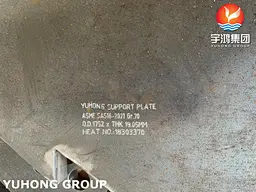
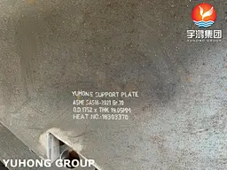
ASME SA516 Gr70 Baffle and Support Plates are the structural and flow-management components inside shell-and-tube heat exchangers that are routinely underestimated in procurement but directly determine whether a tube bundle achieves its design life. SA516 Gr70 is a normalized carbon steel pressure vessel plate specified under ASME Section II, selected for these internal components because it combines adequate strength (tensile 485–620 MPa, yield 260 MPa min) with excellent toughness, weldability, and — critically for baffles — consistent machining response for precision tube-hole drilling.
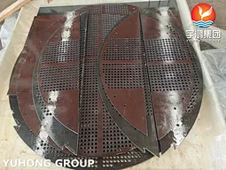
The engineering distinction that matters for specification is functional, not material. Baffle plates direct shell-side fluid across the tube bundle in a cross-flow pattern, increasing turbulence and heat transfer coefficient; their segmental cut geometry and tube-hole layout are designed for flow distribution. Support plates carry larger clearance holes and are spaced at intervals along the bundle span to prevent tube sagging and flow-induced vibration (FIV) damage; their job is mechanical, not thermal. Both are cut and drilled from SA516 Gr70 plate to TEMA dimensional requirements, and both must fit the exchanger shell with minimal bypass clearance. For EPC contractors and heat exchanger fabricators, the procurement risk is not material availability — it is whether the supplied plates will drill cleanly, hold tube-hole tolerances, and arrive with documentation that satisfies the exchanger’s design code.
Application & Compliance: Where They Sit and What They Solve
1. Baffle Plates — Shell-Side Flow Control
Working Scenario: Segmental, double-segmental, or disc-and-doughnut baffles positioned at intervals along the tube bundle. In liquid service, baffle cut typically occupies 20–30% of shell diameter; in gas service, 40–45%.
What it solves: Prevents stagnant zones on the shell side, increases fluid velocity across the bundle, and raises the shell-side heat transfer coefficient. Incorrect baffle spacing or excessive shell-to-baffle clearance produces flow bypass, which degrades thermal performance without any visible material failure.
2. Support Plates — Tube Bundle Mechanical Integrity
Working Scenario: Positioned at mid-span intervals where unsupported tube length would exceed TEMA limits, particularly in long bundles or high-flow shell-side services.
What it solves: Flow-induced vibration (FIV) and tube sagging. Support plates dampen vibration energy before it reaches tube-to-tubesheet joints, which are the highest-stress locations in the bundle. They also maintain tube spacing during bundle assembly and retubing.
3. Service Environments and Material Limits
SA516 Gr70 is the standard choice for water, steam, oil, gas, and non-aggressive chemical services where carbon steel is metallurgically adequate. For shell-side fluids containing wet H₂S, NACE MR0175 / ISO 15156 compliant SA516 Gr70N with HIC testing is available; for aggressive chloride or acidic shell-side environments, stainless or alloy plate grades should be evaluated instead. Typical industry sectors: power generation (feedwater heaters, condensers, lube oil coolers), oil & gas refining, chemical/petrochemical, and HVAC shell-and-tube exchangers.
Technical Specifications & Fabrication Capability
1. Base Material Data (SA516 Gr70, Normalized)
| Parameter | Value / Range |
|---|---|
| Standard | ASME SA516 / ASTM A516, Grade 70 |
| Delivery Condition | Normalized |
| Tensile Strength | 485–620 MPa (70–90 ksi) |
| Yield Strength (min) | 260 MPa (38 ksi) |
| Elongation (min, 50 mm) | 21% |
| Typical C | 0.18% |
| Typical Mn | 0.95–1.50% |
| Plate Thickness Range | 6 mm – 180 mm (custom per drawing) |
2. Fabrication Tolerances & Processes
| Process | Capability |
|---|---|
| Cutting | CNC plasma / laser / waterjet; profile tolerance ±1 mm typical |
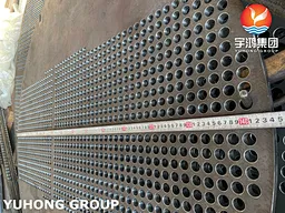
| Tube-Hole Drilling | CNC multi-spindle or single-spindle; hole diameter and position per drawing |
| Baffle Types | Single segmental, double segmental, triple segmental, disc-and-doughnut, orifice |
| Edge Finish | Machined or ground; burr-free for bundle assembly |
| Dimensional Verification | Size measurement, PMI, PT, UT available per project requirement |
3. Baffle vs. Support Plate: Design Intent Comparison
| Criterion | Baffle Plate | Support Plate |
|---|---|---|
| Primary function | Direct shell-side flow, enhance heat transfer | Support tubes, dampen vibration |
| Tube-hole clearance | Close fit (minimize bypass) | Larger clearance (assembly tolerance) |
| Cut geometry | Segmental / disc-and-doughnut per TEMA | Typically full-circle or large-segment |
| Spacing driver | Thermal-hydraulic design | TEMA maximum unsupported span |
| Material degradation mode | Shell-side corrosion / erosion | Vibration fatigue at tube holes |
QA/QC & Certifications: Documentation for Code-Stamped Exchangers
Baffle and support plates are internal to the exchanger, but they are still pressure-boundary-adjacent components subject to code and client audits.
Material Test Reports (MTR): EN 10204 3.1 standard; 3.2 witnessed certification available. Heat number traceability to plate origin.
PMI (Positive Material Identification): Available on finished plates to verify alloy grade before shipment.
Dimensional Inspection: Tube-hole diameter, position, baffle cut angle, and plate thickness verified against approved drawings. Inspection reports provided.
NACE MR0175 / HIC: For wet H₂S service, plates supplied with hardness testing and HIC evaluation per NACE requirements.
Third-Party Inspection: SGS, BV, TUV, or Class surveyor coordination for project-specific release.
Installation & Fabrication Notes (For Exchanger Builders)
Bundle Assembly: Baffle and support plates should be stacked and aligned with tubesheets prior to tube insertion. Drilling multiple plates together in a single setup — a common fabricator practice — minimizes cumulative hole-position error and eases tube loading.
Shell Fit: Baffle outside diameter should be sized to the exchanger shell ID with the design clearance. Excessive clearance allows shell-side bypass; insufficient clearance makes bundle insertion difficult and can damage tube holes.
Welding: Support plates are typically not welded to the shell; baffles may be welded or mechanically secured depending on design. When welding SA516 Gr70, use appropriate carbon steel filler and follow the exchanger’s qualified WPS.
Handling: Normalized carbon steel plates are susceptible to surface rust during storage. Plates should be stored indoors or with protective coating; tube holes should be deburred and clean before bundle assembly.
Comprehensive score